Showing posts with label homemade. Show all posts

Wednesday, January 24, 2018

My first Portativ / Portative / Portativo / Portable Pipe Organ!!!

Here is a photo of the portativ organ that I built.  The pipes were salvaged from a large organ and bought on Ebay.  Everything else was made from scratch and figured out along the way.  Originally, I had piano style keys on the keyboard, but the mechanism that I used seemed to bind the keys where they would stick open.  So I ended up just going to a simpler key.  These are simple button keys on a dowel rod that pushes a block out of the way from the pipe so that the pumped air (you can see the bellows on the back right of the instrument in the photo) can move through the pipe.  The instrument was sealed with caulking.  The first 2 times I put it together, there were leaks or problems with the mechanisms or keys.  I finally feel that it is where I would like it to be now.  The wooden pipes give a hollow steamboat sound.  The metal tabs on top of the pipes are for tuning. 

I have a second set of metal pipes that I plan to use to build a second portative organ.  I hope to use keys of some sort for that one.  If it is successful, then I may retrofit this one with keys again but for now, it works just fine.  

The downside of the buttons is that the dowel that holds them has to be pressed pretty hard and I worry about the dowel breaking if someone tried to play it and put pressure on the button at an angle.  I did see someone build a portative where there was tubing after the key and before the pipe - that method would certainly allow a more flexible key bed layout.  For mine, there is an angled piece that connects the bottom of each button to the lever on the pipe - it was rather cumbersome to make and took a lot of sanding to get things so they would not bind to the surrounding pieces.   The valve that opens and closes has a piece of cork covered in Chapstick to block the passage for air leaks.

Wednesday, December 9, 2015

The Roland CPE-800 and VCA-800

I recently acquired a working, vintage Roland CPE-800 and VCA-800 from my friend Jacob Graham.  His obsession with early 80's Roland gear had led him down the rabbit hole to this beautiful and interesting piece of gear.  He came across it on EBAY and bought it to add to his Roland studio (which consisted of all Roland gear at the time, nothing newer than 1983).  After a few years of owning it, Jacob found he was not using it much and put it up in a local store NYC music store where no one wanted it, and it sat for another year.  I found out that he was selling it when he told me that the music store asked him to come and pick up this large paper weight that nobody wanted.  I immediately said “Oh – your actually selling that?  I will buy it!!!”
 
There were very few of these made and hardly any in use today, from what I can tell.  There are not many references to the CPE-800 online.  There are few photos.  Where there is a reference, it is always a vintage ad or someone saying how obsolete this equipment is.  They could not be more wrong.  People have admittedly destroyed these, piecing them out for parts for the Jupiter 8 or TR-808 – which is a shame and tragedy. 
 
 
This is not a rant about using some obsolete equipment and trying to do things “old school”, somehow believing that you are preserving some piece of history in the process.  Once I had heard about this piece of gear and understood what it does, I was blown away that something like this even exists.  With a modification, I saw a potential to have one of the most versatile, stand-alone modular synthesizer control surfaces ever made.
 
 
In many ways, the technology that this product was intended for is indeed obsolete.  When this product was introduced, it was intended to be used for the motion picture industry.  It would sync to SMPTE time code.  It would allow automated volume control over 15 channels for up to 99 hours provided that it would not run out of memory.  Memory usage only occurs when changes occur – in other words, if the levels stay the same, no memory is used for automation.  The original list price was close to $8,000.  Jacob had bought his for a small fraction of that price and relayed the same price to me. 

In a conversation with someone who worked at Roland during the time of the release, it originally had a problem with the SMPTE time code where the 1’s and 0’s were reversed and it would not work with other SMPTE products but would work great with itself.  This was fixed in software, but the first impression to the industry had already caused some damage and sales were low.  Roland only had schematics and a user manual for this.  No service manual was ever made for this product.  The user manual mostly talks about using the CPE-800 with the VCA-800, but there is also several references to using it as a lighting control and putting it in“scene” mode.
 
 
When used in conjunction with the VCA-800, to call this a mixer would be a false statement.  Even though it looks like a mixer, there is no summing amplifier so channels are not combined in any way.  Each channel has a single VCA, with its own input and its own output...     To call this a controller is an understatement. The board unit by itself automates CV’s (control voltages) that span from 0 to 10 volts.  This is much like the Flame knob recorder or the Modcan CV recorder except it has 15 channels instead of 2-4 channels.  Although the CPE only has a fixed timebase (unlike the Modcan and Flame, where there is a variable speed), the length of the recording can be anywhere from less than a second to 99 hours!  This can also be looped, paused, or restarted...    
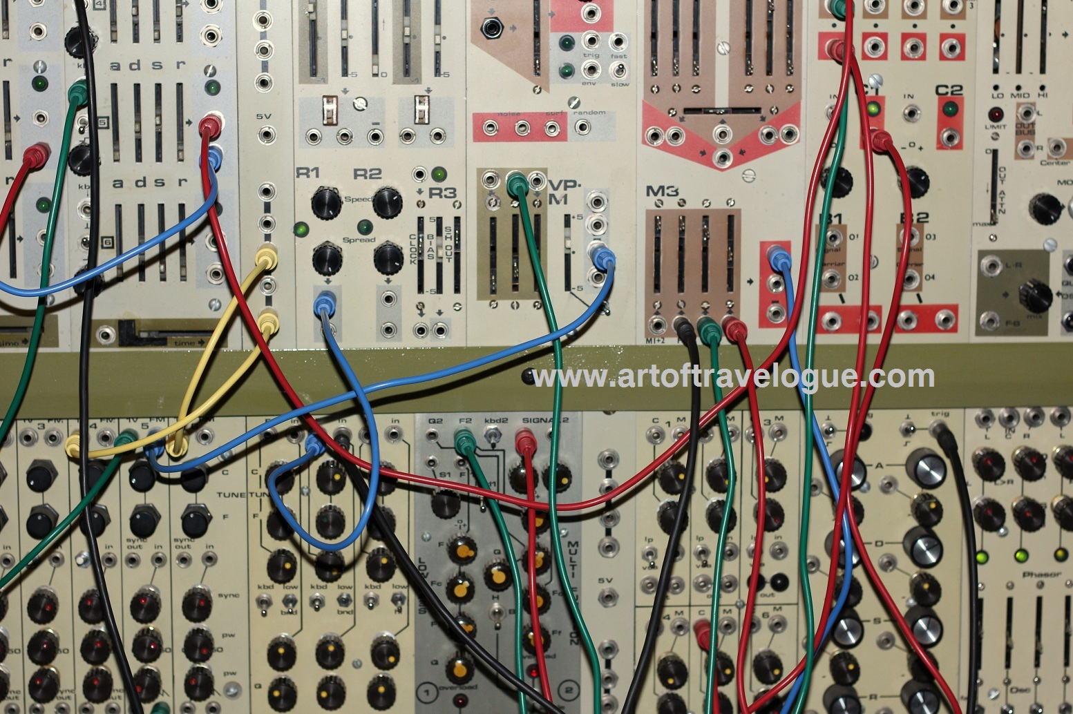

These voltages go into the VCA-800  box (shown in the photo above) to control the amplitude/volume.  You can use the faders manually (and they are high quality Alps 100mm faders!), or you can record or playback the changes that you make over time.  The faders are not motorized, but there is a nice pair of LED’s that show if the memory value is higher or lower than where you have the channel set. With a modification that I did, this is an amazing CV controller, can be used with ANY modular equipment, and blows away most modern controllers that are being made today.  15 channels can be used as level controls or voltages, or both, to send signals anywhere in your modular patch.  My modification is shown in the photo - it is the grey rack on top of the VCA-800, with a row of 15 attenuators and a row of 15 CV output jacks.

 
On a technical note, the VCA’s are DC blocked so the lowest frequency that they pass is around 15 Hz.  This cannot pass LFO’s to other modules through the VCA-800, but you can use the voltage outputs that I added to control VCA’s that are not DC blocked and can pass LFO’s or other CV signals.  I added attenuators to each of the 15 voltage outputs so I can scale them down to work with various modules.  I also added another modification where I can start and stop this with a gate signal from an analog synthesizer – so it can be used as a 99 hour, 15 channel, arbitrary envelope generator.
 
 
I would love to buy more of these, add my modification, then sell these as a control voltage source or offer a modification box as a service.  The problem is to find another.  Contact me if you have one of these that you wish to sell.


Video examples of this unit in action will be posted soon.  I just need to edit some footage together.

Thursday, February 13, 2014

Magnetic Table DIY

I get a lot of emails and comments concerning the Magnetic Table CV Controller that I built and demonstrated here:


I wanted to add a few notes on the construction and process of building one for those who wish to build one for themselves. 
 
I built it out of spare parts that I had lying around, plus a cheap wooden box that I bought at the craft store, then stained it and made it look older with some raw umber and shoe polish.  Originally, I just fastened an aluminum rod on the end of the joystick for the pendulum arm, but it was a little more wobbly than I wanted it to be and it easily loosened to the point where the subtle changes in position would not transfer to the joystick motion.  I eventually took the joystick apart, removed the "stick" and machined the end of a long aluminum rod to match the end of what was inside of the joystick so it became one long continuous shaft.  Most of this work was done using a lathe, a file and scotch brite for the final smoothing of the end.
 
The arm that holds the pendulum above the table was something that I had salvaged out of a discarded store display from a temp job that I worked at years ago.  It was sitting around my shop for years before I put it to use. It needs to be adjustable for a few different reasons:  1) if you want stronger magnets, the easiest way to make this happen is to stack them.  When you stack them, you need to adjust the height of the arm to compensate for the height of the magnets.  2)  At one time, I had not used it for a few months and when I went to use it, I noticed that the magnet at the end of the pendulum had broke free of the epoxy glue and the magnetic attraction over time had been enough to break that bond.  Since then, when it is not in use, I adjust the arm so the pendulum rests on the table and no additional forces are trying to pull the magnet free of the epoxy bond.  I have been asked where one could obtain the parts to make a similar arm.  The closest thing that I have found is available at Edmond Optics:  http://www.edmundoptics.com/optomechanics/optical-breadboard-components-laboratory-tables/posts-post-holders/articulating-arm-mounting-systems/1369
 
where synthesizer enthusiasts have talked about building their own version of this.  The discussion came up of having the table be curved and maybe a wok could be used.  This is a great idea and though it would certainly eliminate the need to stack the magnets at different heights for the outer extensions of the pendulum, it would drastically cut down on the ability to see the center positions of the pendulum and might not be as visually satisfying.  Honestly, stacking magnets is not a big deal.
 
One last note/comment on the electronics inside of the pendulum.  I simply have a 9V battery going into a couple of LDO linear regulators with input and output capacitors for each X and Y position.  The regulators make the position consistent and repeatable as the battery dies.  Realistically, I change the magnet position so often, that consistency and repeatability are not really practical issues.  Just running the 9V battery through the joystick attenuators would be sufficient.  You could also easily modify this to add oscillators, filters, etc into the box.  I left mine as a CV controller to modulate external oscillators, filters, etc. The knobs on mine strictly limit the range of the joystick itself by adding series resistors in the voltage divider.  One could also process the CV through an opamp and make the knobs control offset and amount.

Saturday, March 2, 2013

The Yamaha CS-20M is my favorite synth...

 
So let me be clear on something upfront.  I have often said that the Yamaha CS-20M is my favorite synthesizer.  To be truthful, mine has been modified and so I should say that my modified CS-20M is my favorite synthesizer that I have played.  The CS-20M is still a great synth without the mods, but many of my favorite sounds use one or two of the mods.
I like it so much that it has made its way to countless shows that I have performed, even though it is heavy to lug around and I don't have a good case for it.
 
So you might ask, "What makes this synthesizer stand out above the other synths?".  I am glad that you asked and I will try to answer this.  The CS-20M has 2 oscillators, 1 VCF, and blah blah  blah...  (you can find the specs on any synth or vintage synth website. )
 
One of the unique features of the CS-20M (and much of CS series) is that the LFO waveforms are selectable within each section; for instance, VCO 1 can be modulated by a sine LFO, VCO2 by a square LFO, and the VCF by a sample and hold - all going at the same rate. Furthermore, the LFO rate ranges from rather slow to audio. 
 
 
Another great feature is that there are 8 memory locations to store and recall settings.  This is great for live performances because I usually do about an 8 song set and can easily have a new sound for each song. 
 
The VCF can function as a high pass, band pass, or low pass filter, plus there is an option to mix in the SINE wave from VCO1 after the filter.  So you can have the SINE fundamental and then use a high pass filter or band pass filter to add a section of harmonics on top of the SINE wave.  Many complaints have been made that the filter on these will not oscillate when the resonance is up and that it sounds too smooth.  While it is true the the filter does not go  into self oscillation, it sounds very musical and smooth - I would compare it to a Nord Lead. 
 
The modifications that I have added were done around 1994 or so.  I tapped into the modulation pots for VCO1, VCF, and VCA, and connected these to a input jack that would normalize the connection back to the stock circuitry when a jack was not connected.  I also tapped the VCO2 output and the noise generator output and put a jack option for an external input into the filter.  This allows me to cross modulate the oscillators, modulate oscillators by noise, modulate the filter or amplifier in different ways, and run external signals through the filter.

I usually have VCO2 modulating the VCF through the jacks that I connected to the circuitry.  This allows for a lot of harsh sounds, especially when the resonance is set pretty high and VCO2 is tuned an octave or a fourth down from VCO1.  Many times when I play live, this patch cord is in place. 

Even though the filter does not go into oscillation by itself, you can sort of trick it by sending the headphone output jack into the filter input jack that I added.  This is not exactly the same as a self oscillating filter, but it gives strange ringing sounds that can be really neat and useful.

A few years ago, I had an opportunity to buy the slightly older brother of the CS20M, the CS40M, at a fair price.  I did.  I will create another post in the near future that outlines some of the differences between the two synthesizers.  I prefer the CS-20M, but this is mostly due to the mods which can't be done as easily to the CS-40M.

Monday, January 7, 2013

A new video post of the Magnetic Table

Here is a video that I made of me demonstrating the Magnetic Table, a CV controller for modular synthesizers.


I wrote about the Magnetic Table in this post: http://artoftravelogue.blogspot.com/2012/02/magnetic-table-cv-controller.html

Monday, November 19, 2012

Patch Cable Rack Solution.

Storage of cables can be a problem - especially when you need access to them in different parts of the studio.  I came up with this portable cable rack for this purpose.  It holds the patch cables for my modular synthesizers and can move out of the way if I need the space.  This beats cables hanging in the way.

Tuesday, October 23, 2012

Studio Organization

In the past, I have used hanging shoe organizers to store effects pedals and other small electronic devices.  In the new studio, I have built some custom shelves to take the place of these.  Here are some photos of the process...


On the left, the photo shows the various pieces of the shelf.  The bottom of each section of the shelf is covered with felt.  The photo on the right shows various scraps of wood being glued into the top of each cubicle.  These random surfaces will allow the shelf to also act as an acoustic diffuser.  These wood scraps were then painted to match the shelf and the wall as seen below.

Wednesday, September 5, 2012

Setting up a new workspace


 As I put back together the studio, I am rearranging and reorganizing - mostly because I would like to have all the modular equipment closer together and have minimal gaps inbetween the different modular synthesizers that I own.  Here is how I made my own stand that will allow all the equipment to be at the same angle, regardless of size or shape.  I do this by first making a plywood table - reinforced by 2"x3"s, with aluminum tubing for the legs (this table is sturdy enough to support my weight, so I know that it won't have a problem with the modular synths)  I figure out what angles that I would like the equipment to rest and make patterns for each piece of equipment.  Next, I cut out pairs of wooden shapes based on the template patterns to be used as arms for the equipment to rest on - these are shown in the photos on the left.  The pairs are linked together with a short length of 2"x3".  At first, they are loose and moveable.  Equipment is placed on them and they are moved into the desired position.  Each pair of shapes is then fastened to the plywood table with screws.  Finally, the entire thing gets 2 coats of black paint and 2 coats of polyurethane.

After everything is fully dried, I am able to place the equipment back on the racks.  I put a hacked ultimate support stand inbetween the Modcan and Synthesizers.com systems. 


Saturday, August 11, 2012

Monolith modular synthesizer


Several years ago, I bought a modular synth from a friend that needed tons of work.  The possible features of this synth made it very attractive, however, and I was willing to take the risk of buying it without any guarantee that I would be able to fix it.  Originally, the synth had an attached keyboard and joystick.  I have not been able to fix the keyboard section of it yet, so I modified the case so that the keyboard is in a separate enclosure.  One the keyboard part, there is lettering that reads "Monolith II".  Other than that, I have no clue what the origins of this synth are.


The Monolith II has many useful features that I have not seen in a lot of modular synthesizers. A description of each module is found on my flickr page (see link on right side of this blog).  Many of the modules were cryptic, with single letters indicating what their function is:  M for mixer, VP for voltage processor, C for comparator, R for random generator, etc.  In addition to this, there are several mixers, so they are called M1, M2, M3, etc.  The photo on the right shows a close up of some of the modules:  Voltage processors have bipolar attenuation and bipolar offset with built in meters, The external input processor has a built in mic, compressor, voltage follower and trigger detector. 


Click on any of these photos for a larger view.

Tuesday, February 28, 2012

Clock input for the DR-110


This is a response to the comment from an earlier post on modifying a Roland DR-110 drum machine for a clock input. Here is the PCB layout from the service manual.  I added the section of the schematic that shows the clock.


To modify the clock, I simply broke the connection between the clock generator and the rest of the circuit (in the DR-110 schematic and PCB above it is shown in red), then I replace it with a switch and a jack. The switch can reconnect the clock circuit to the board so the tempo knob works again, or it can switch to a jack to be connected to an external clock. If you try to attempt a modifications like this, make SURE that you understand which node is the clock_source and which node is the clock_destination of the broken link - you don't want to miswire this and accidentally feed an external clock into a clock generator circuit!  In the above example, the side closest to U2 is the clock_source.  My master clock is coming from a Garfield Mini Doc so I have lots of clock options to choose from.  Some divisions work better than others.  For the DR-110, the "12" division output (12 pulses per quarter note, I believe but I have never verified this) seems to be in perfect sync with all of my other gear.

This method can be used with other drum machines or sequencers that don't have a clock input, provided that they have an internal analog clock generator.  A word of caution though:  not all clocks work at the same voltage level: Do NOT try to directly clock something with an external clock without first understanding what speed and voltage levels it toggles between!  Use an oscilloscope with a x10 probe (if available) to tell you what the clock needs to look like in order to sync up to the device, then try and match the external clock signal as close as possible to the measured internal clock.  For some machines, an additional transistor may have to be added to change the voltage level or clock pulse width, but I will not go into details on using a transistor as a switch in this post - there are plenty of examples elsewhere.  For a machine like the DR-55, I find the clock source that works the best to be sending a 16th note clock into a decay/release envelope circuit, then into the external clock input of my DR-55.  I did not need to do this for the DR-110 because the clock was close to the same levels that the Mini Doc generates.

This being said, modify your equipment at your own risk.  I have done modifications that work fine, then you plug the wrong type of signal into the jack (Voltage could be too high, or you create a current path that should not be there) and because the internal circuitry was not designed to handle this, components fail.  Without being too crazy or obsessive, treat equipment and circuitry with caution, respect, and understanding and your modifications will work fine.

Monday, February 13, 2012

Magnetic Table CV Controller

Here is one of my designs that I based off of a magnetic pendulum toy.  The toy consisted of a dangling string with a magnet on the end of it; then it hovered over magnets on a table that either repelled or attracted the string magnet; the stringed magnet then maneuvers around in crazy patterns due to the position of the table magnets.

There are 2 control voltage outputs for this device; one for the X axis, and one for the Y.  They vary from 0 to 5 volts.  These can be used to change any parameter in a synthesizer or effects system to make interesting sounds.  For instance, the X axis could control the pitch of an oscillator, while the Y axis could control the volume.  Another example could be the X axis controls a delay time, while the Y axis controls the feedback of the delay unit.  A third example (and a little more abstract) is to have the X axis control the length of a sequence pattern, and the Y axis control the tempo of the sequence.

One interesting thing about using the magnetic table to control sound is that when the pendulum passes over a magnet with a pole that attracts the pendulum, it overshoots a bit, then swing back toward the magnet and overshoots again, continuing to oscillate in a damped, simple harmonic motion.  If the magnet is stronger (you can use larger magnets or stack them to make them have a stronger attraction or repulsion), then this oscillation is faster.

For my design, I mounted an upside-down potentiometer-joystick on an arm above a plate of steel, then machined a long, aluminum rod to replace the shaft that was inside the joystick. At the end of this rod, a cavity was made and a powerful magnet was epoxied into the cavity.  This magnet can freely hover over the steel plate.  If  magnets are placed on the table / plate, then they can repel or attract the rod (and therefore move the joystick) based on their position and polarity.  The potentiometers on this joystick are wired as voltage dividers/ attenuators for DC voltage.  There is a 9-volt battery inside going to a linear 5-volt regulator, then to the divider.  The knobs on the front of the box control offset and range for X and Y.

Tuesday, January 17, 2012

The Casiotone

So you can play a violin sound, piano, or fantasy!
Where do we draw the line between our imagination and the limitation of the equipment, instruments, and our ability to play them? Is it possible to transcend these limitations.

I recently read an article on synthesizers where someone was asked if ANY sound was possible in synthesis.  The reply was yes. I admit - there are times when I come up with a sound that fully beats all expectations that I had in creating that sound.  In other words, it is beyond my imagination or fantasy.  But then again, there are times when hours of fine tuning and adjustment leads to a sound that falls short of everything I had hoped for. 

I approach synthesis in a very practical, logical, and strategic way.  Maybe it is the engineer in me.  I don't subscribe to the point of view that randomly plugging in things and turning knobs will get you this "wacky" sound.  Each and every patch has a purpose and method and objective.  This is not to say that I don't experiment or try new ideas... but the ideas have an objective and purpose. 

Most all of my experiments start with a question: Sometimes my experiments are things like: "What if I made a through-zero oscillator out of these 2 VCO's into a four-quadrant multiplier out of this VCA and VCF, then modulated a 3rd VCO?" or "What if I take the output of this VCF, run it through a Big Muff, then feed it back into the 2nd input of the VCF and control the phase and gain of the feedback loop" or "What if I build a stringed instrument that uses chimes for sympathetic vibration, but the main pickup is closer to the chimes than to the strings?"  Maybe with this kind of logical experimentation, there is not room for a "fantasy" sound.  Maybe the search is on, and I need to determine what I fanasize about. 

My current fantasy, musically, is not a sound, but a keyboard controller...  one that looks like a piano keyboard with maybe a couple octaves of keys that move up and down, but also slightly side to side and forward and backward.  Each key would spring back to a stable central position when not touched.  This keyboard would respond not only to velocity and note on/note off but also wiggle movement side to side, wiggle movement backwards and forwards, aftertouch/pressure, finger surface area, and finger position along the length of the key!  This is very posible with the technology available with modern accelerometers and cap-sensative switching, but is a mechanical engineering nightmare and would require a lot of planning, clever layout, and coding of multiple microprocessors.